HPU for MOD

HPU for MOD

HPU for MOD

 All info below, just needs formatting and optimising:

Richard Renfree supplied following info:

– End user: Leonardo Helicopters, but Rotec are supplying to Keyford

– Project discussions started in Nov 2019

– Has been in the making from May 2020

– For use in the military: testing the system that assist helicopter landing on military vessels


  • For use with Mineral hydraulic fluid based upon AeroShell Fluid 41.
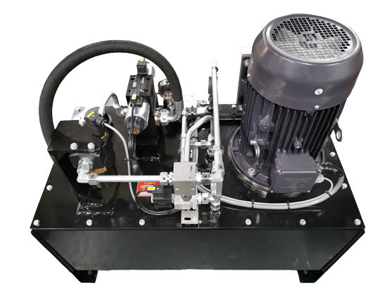
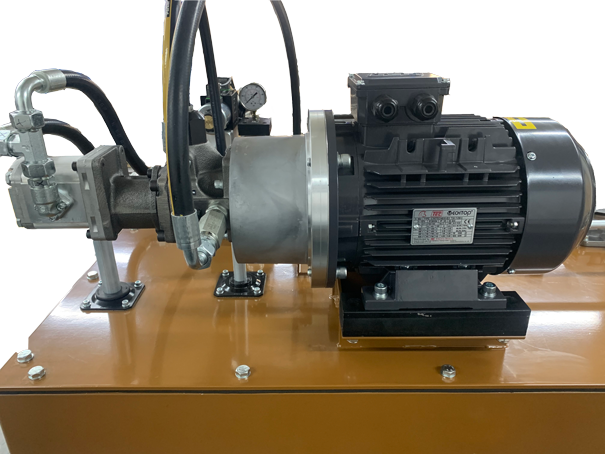
  • Electric motor 3kw, 220VAC 60HZ,  1 Phase.
  • Fixed delivery hydraulic pump to supply a nominal 10 L/Min at 140 Bar.
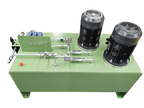
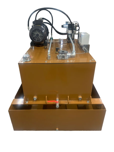
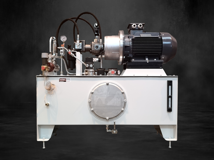
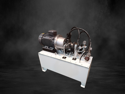
  • Hydraulic reservoir – Nominal 70ltr Cast Aluminium base with a Aluminium reservoir lid fitted with the following items:-
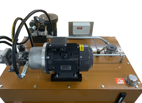
    • Electric motor & Pump set (Above) vertically mounted (Pump below reservoir lid)
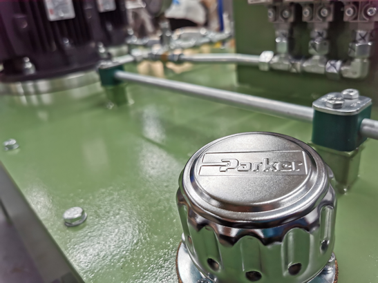
    • Filler breather
    • Visual oil level sight gauge
    • Pressure filter, with visual filter condition indicator and internal by-pass valve
    • Return line filter, with visual filter condition indicator and internal by-pass valve
    • Hydraulic manifold assembly with:-
      • Pressure relief valves to limit the maximum pressures
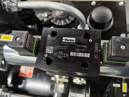
      • Electrical Un-load / Loading hydraulic control valve


Hydraulic reservoir – fitted with the following items continued:-


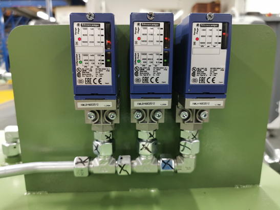
    • Electrical Low oil level switch
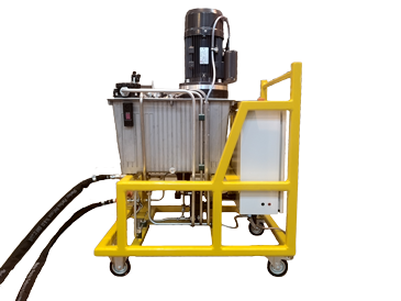
    • Frame to support power unit and accumulator fitted with castor Wheels – two fixed and two swivel castors incorporating brakes & fitted to the reservoir  feet.
    • Steel hand pump to achieve the highr system pressure requiremnt of 210Bar. Max working force required at 210Bar using 600mm lever is 25kg.
    • Manual decompression valve
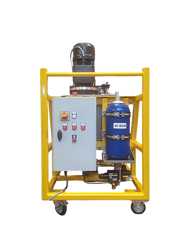
    • 5 Litre accumulator precharged to 80Bar with safety block for safe isolation/discharge.
    • 4 x 20 Litre containers of Aeroshell 41 hydraulic fluid***


Also fitted to the power unit would be:-


  • Quick release couplings and connecting hoses to accept harpoon test frame. (2 off 5 meter hoses)
  • Electrical control panel – Motor starter and 28vdc supply for harpoon test frame
  • Electrical control panel to be mounted on power unit incorporating.
  • DOL Starter with Thermal magnetic circuit breaker
  • Lockable panel isolator
  • Emergency stop – Dual chanel safety monitoring relay for the emergency stop circuit
  • Panel indicator lamps for oil low level, motor overload and E stop healthy
  • 28VDC supply for harpoon test rig.
  • Panel mounted digital pressure display


HPU for Wessex Water

HPU for Wessex Water

Wessex Water HPU

Get Info from Andy Rimes


Info from bed Foskett:

It is used by Wessex water in their “sieve room” (no idea) to power cylinders that open and close a knife valve to control water flow. Attached picture illustrates a knife valve (not sure if it is the actual one or not). The HPU consists of 2 pumps each powered by a 4kW motor and each delivering 12 litres per minute.


I think it might be connected to a bank of 8 54 litre accumulators (I believe Alex knows about this).


HPU for a composite yacht mould

HPU for a composite yacht mould

Sorcerer Machinery HPU

Adrian Derbidge: has drawings related to project.

Is used for powering a Yacht composite mould machine

2 speed hydraulic control

More info from Andy Rimes


HPU for a Special Alloys Producer

HPU for a Apecial Alloys Producer

Rotec was commissioned to manufacture a Hydraulic Power Unit for a British high-nickel alloy specialist. The customer produces special metals for a variety of industries including Aviation, Automotive, Marine, Oil & Gas and more. The project was referred to Rotec by another hydraulic engineering company.

Rotec produced a double pump arrangement with the main pump working at 23 LPM and pump 2 at 27 LPM.  This design provides a regenerative flow to the cylinder where when the cylinder is extending, it’s using the flow from the annular side of the cylinder directed to the bore side to make the cylinder extend faster, to allow a faster production rate.  The HPU drives a hydraulic cylinder which pulls lengths of hollow bar over a cutting tool to machine the inside diameter of the bar.  A new unit was required, to replace an old existing one which was leaking oil and was inefficient.

Rotec designed and built the unit working to an existing hydraulic circuit drawing supplied by the customer. The unit is designed to withstand the tough working conditions of a busy foundry and includes a bundt which helps contain any leaks during maintenance.

The unit has now left Rotec’s workshop and is ready for installation.


Technical Specs:

  • Main Pump: 23LPM
  • Pump2: 27LPM
  • Working pressure: 27 Bar
  • Electric motor: 4kW
  • 450 litre reservoir and 495 litre bundt


HPU with a 250 litre reservoir

HPU with a 250 litre reservoir

Project background: How did we get this project. What is the unit used for? (Richard Lang or Dale Lockart can find out)


  • Technical Specifications:
  • The HPU consists of a 250 litre reservoir.
  • 5kW 6 pole electric motor
  • Bell housing and Starex type coupling
  • Double Pump:
  • Berarma variable delivery vane pump with a maximum displacement of 16cc/rev, which has been de-stroked to 9 cc/rev to deliver 8 lpm at 950 rpm
  • Coupled to the back of the Berarma pump is an Elika group 2 gear pump of 11.4 cc for the conditioning system which will deliver 11 lpm of flow through the system


The Berarma vane pump is a pressure compensated design with high pressure cut off control and a high pressure setting of 230 Bar (When the pump is dead headed against the pressure port closed servo valve and producing Zero flow, the pump pressure is 230 Bar, producing up to 8 L/min up to 210 Bar dynamically). The pump is also fitted with an integral pump un-load valve (24vdc single solenoid, 2 position spool control directional control). This will be to unload the main variable delivery pressure compensated pump to its minimum pressure setting of 25 Bar when the solenoid is de-energised.

The main relief will be set to 260 Bar. Also included is an analogue pressure gauge, inline check (non-return) valve and 2 micron pressure filter with electrical indication switch. A second electrical unloading solenoid valve will be fitted downstream of the check valve and filter to facilitate unloading of hydraulic pressure when the unit is turned off.

From the Elika gear pump, the conditioning system will have a shell and tube type heat exchanger and a second, 10 micron tank top filter. A 4.5 Bar check (non-return) valve will be installed as a bypass relief valve to protect the heat exchanger. A temperature-controlled water solenoid valve will be fitted to regulate the flow of cooling water through the heat exchanger.