Rotec’s repair and overhaul service reduces running costs by 10% at leading manufacturer

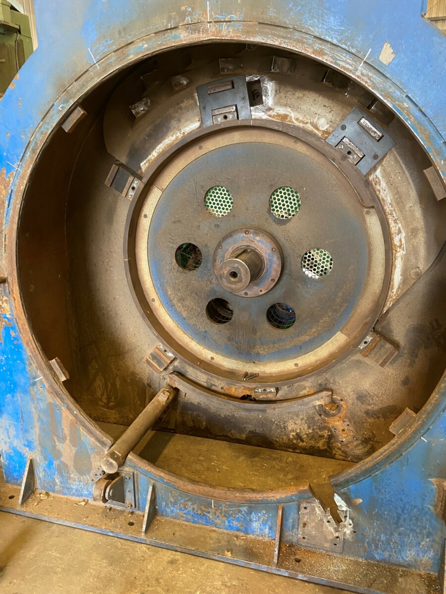
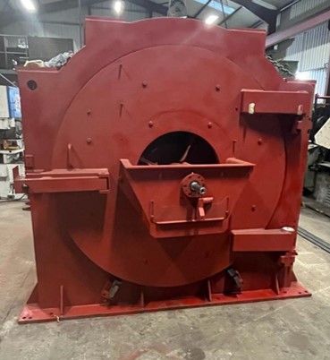
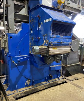
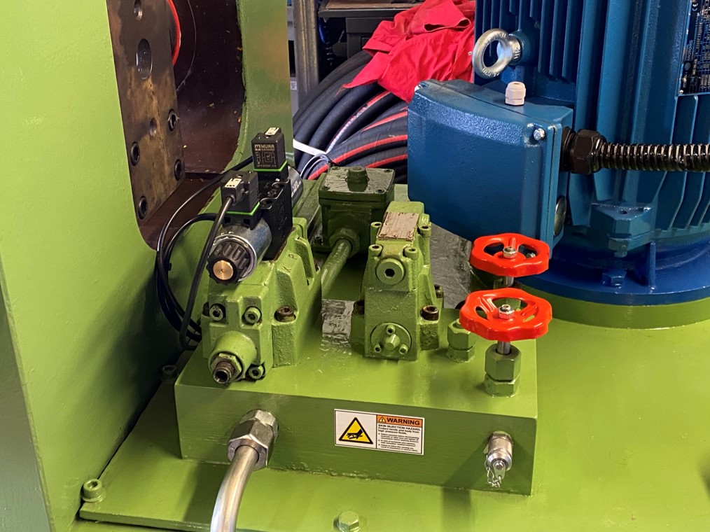
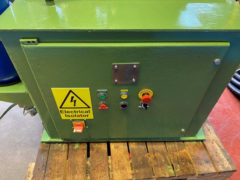
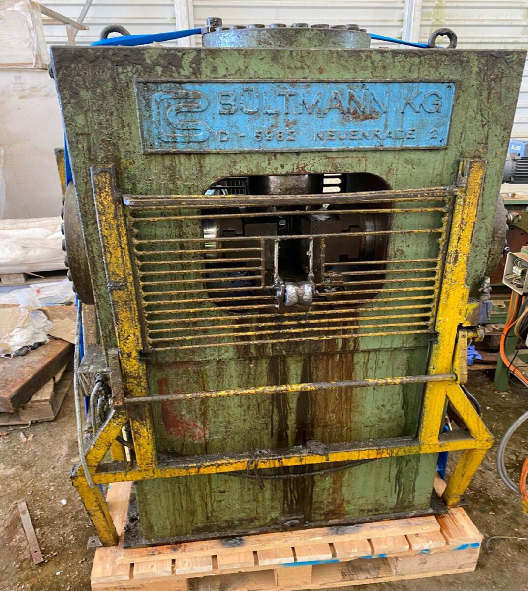
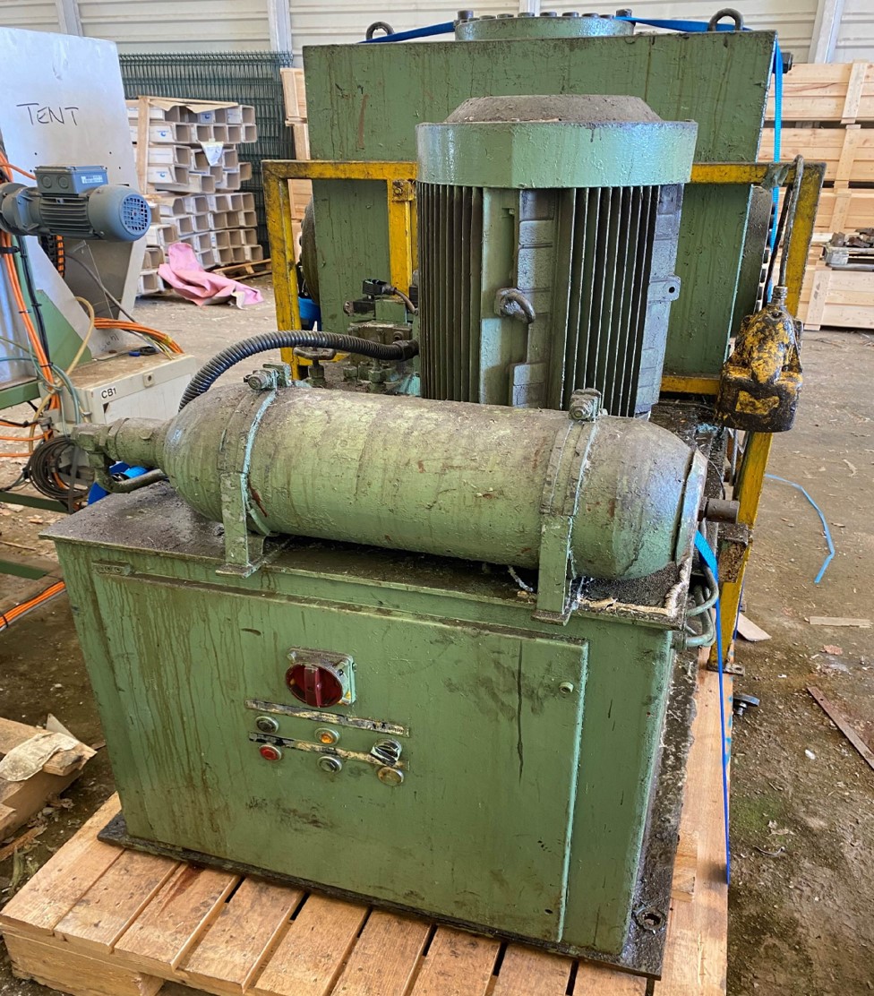
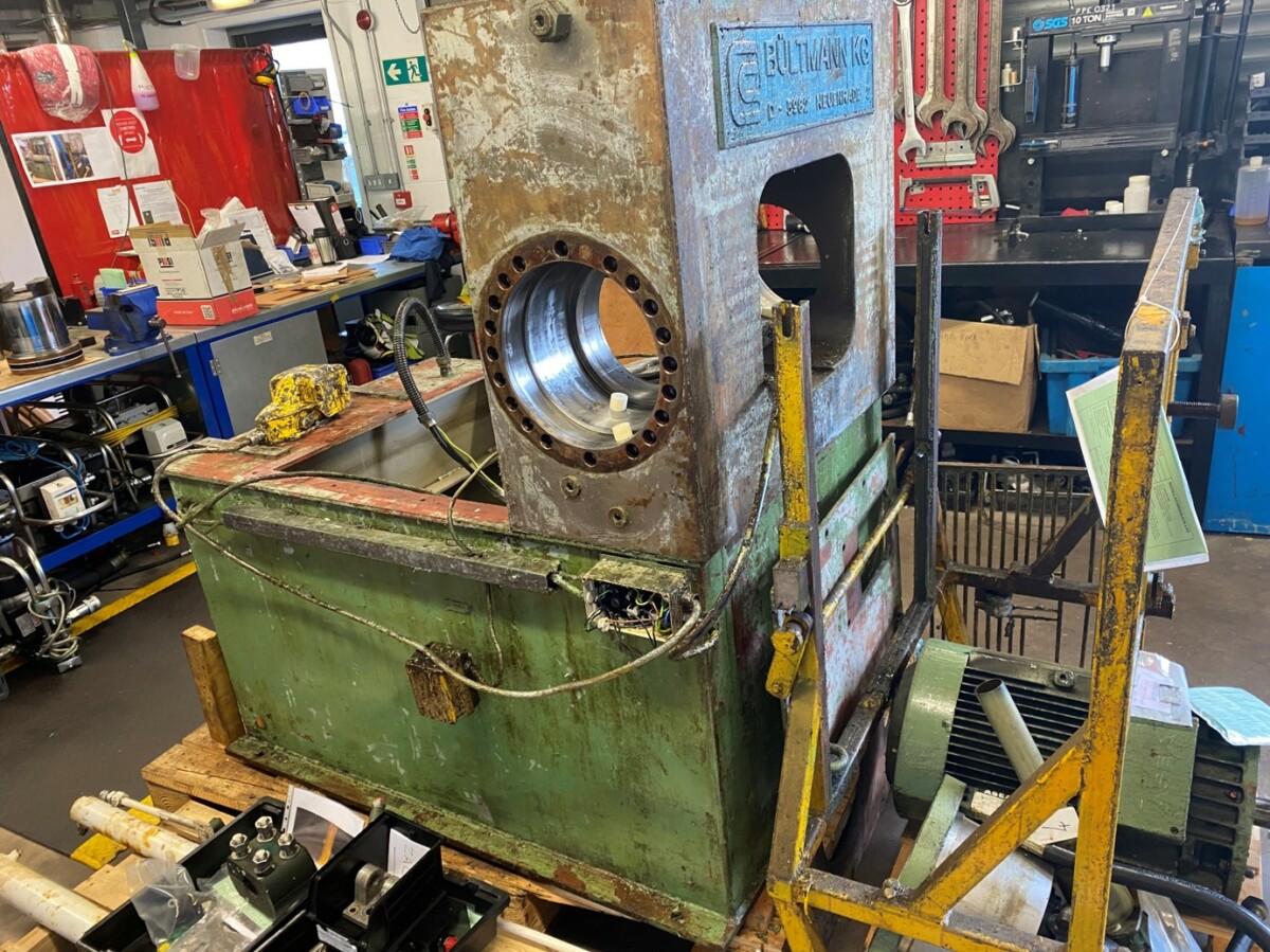
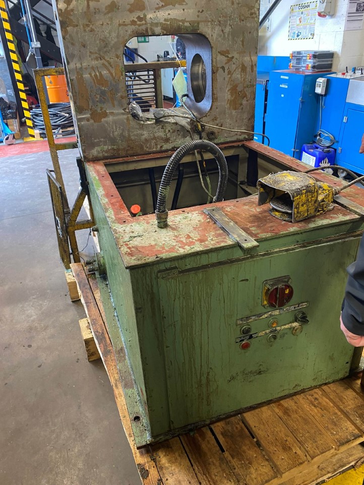
Machine prior to overhaul

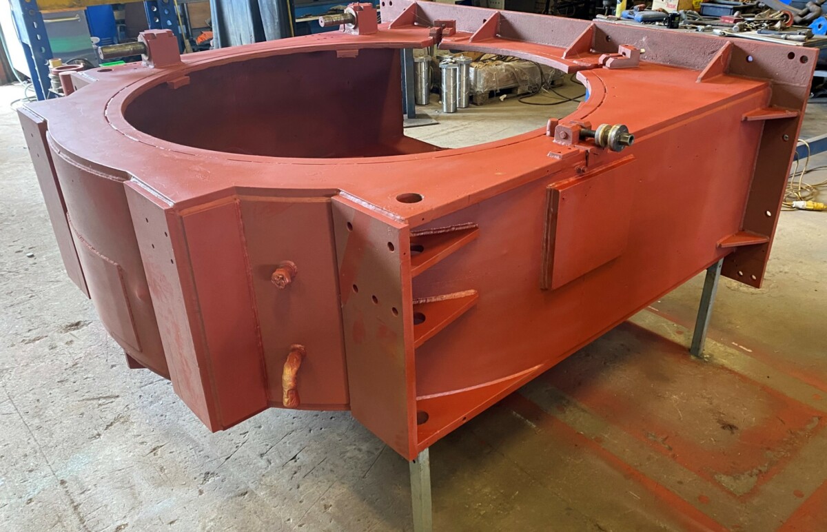
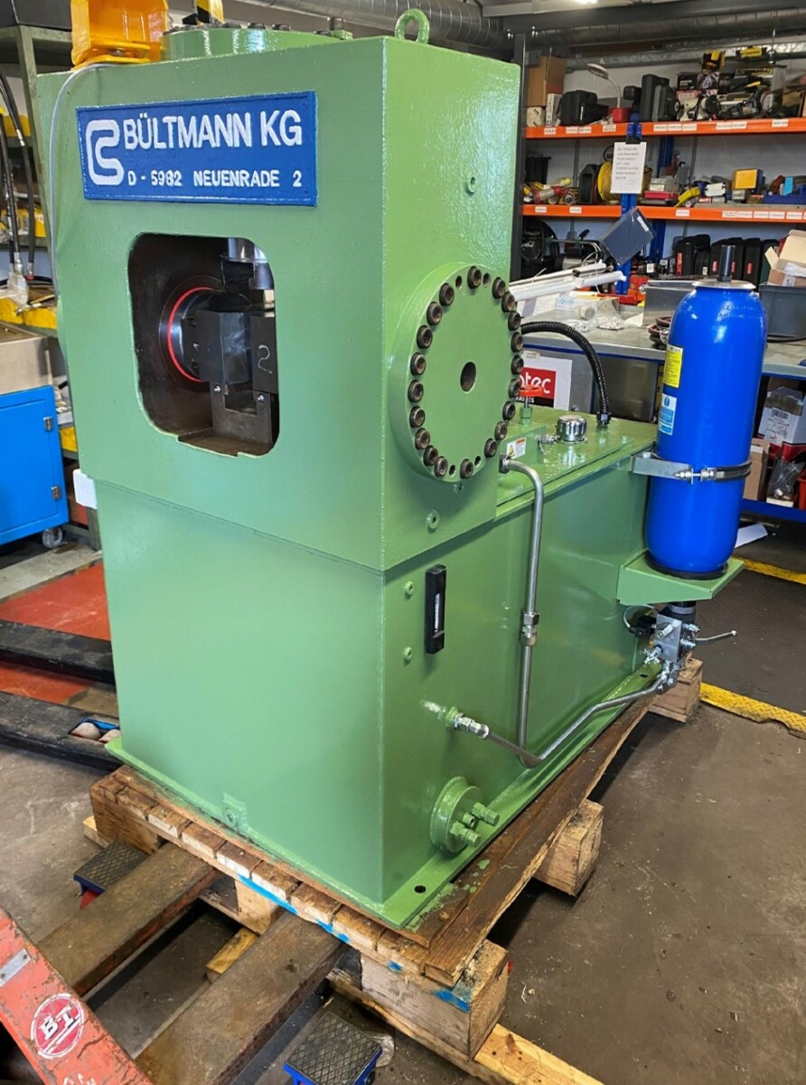
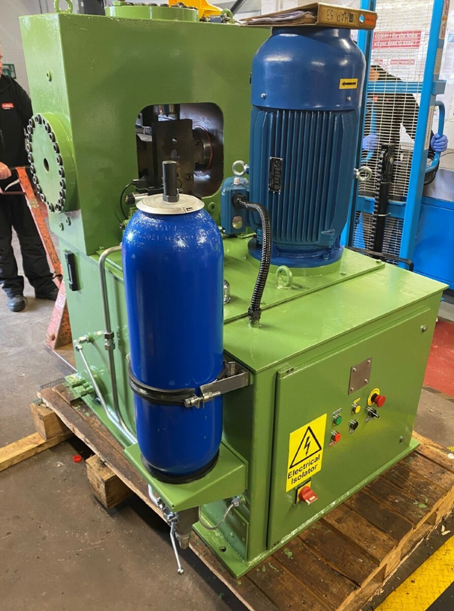
Overhaul completed, outer door refitted and ready for re-paint
Following a major failure during operation, a large flooring, MDF and OSB manufacturer asked Rotec to carry out extensive repairs on an industrial wood chipper.
Owing to the failure occurring whilst the machine was in use, the Maier Wood Chipper machine had suffered severe damage internally and so required a thorough repair and overhaul service.
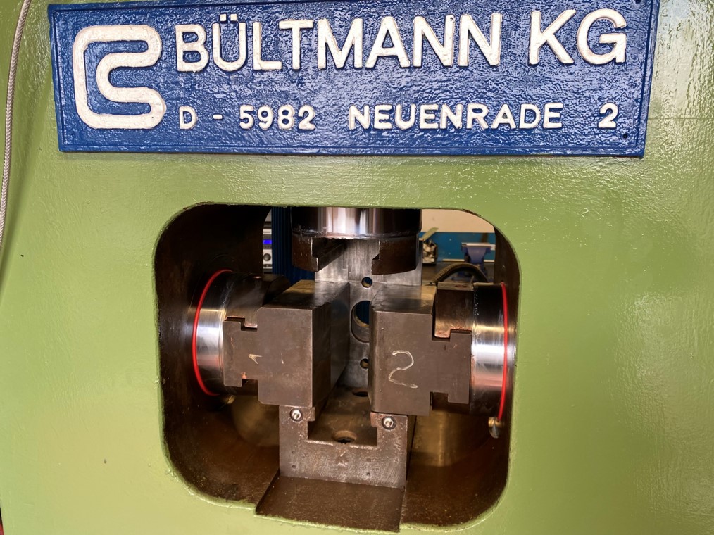
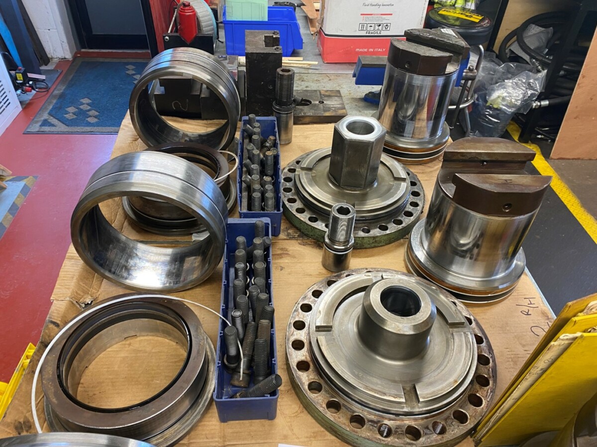
After Rotec engineers stripped the machine and checked all components, it became apparent that the shaft bearing sleeves had failed, worn the housing and as the blades had come away during the failure, many internal parts were damaged and required either replacement or upgrading.
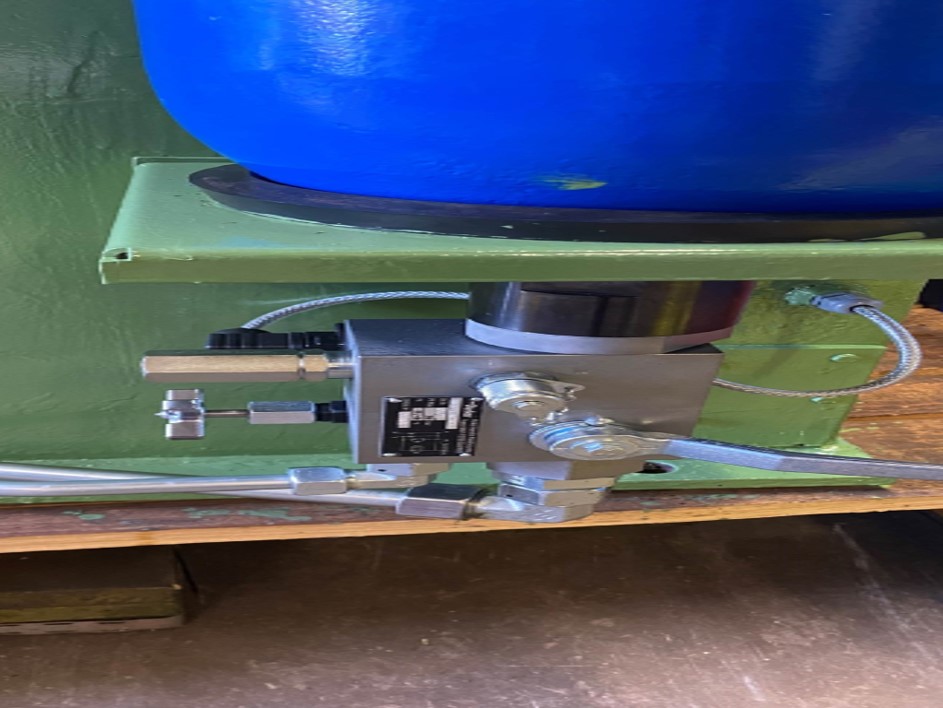
As the customer had issues with levelling up the impellor blades, Rotec checked the laser alignment and then ‘clocked’ the rear datum locating ring support pads on the machine. The support pads were found to have a 0.7mm difference in their positioning which, may have been a contributing factor to the issues leading to the initial failure. On discussion with the client, it was decided to build up the lower blocks and design and build a tool for machining the pads in-situ.
Once the chipper had been repaired, overhauled, re-painted and fitted back onsite at the customer’s facility, the client was so pleased with Rotec’s workmanship and project management that Rotec have now taken delivery of another unit from the same workshop for a complete overhaul.
The Engineering Managing of the flooring, MDF and OSB manufacturer has since reported that the overhaul and rebalancing of the machine is so good that the company is achieving a higher output rate and saving 10% on the machine’s previous running cost.
Laurence White, Business Development Manager for Rotec Hydraulics Ltd, commented;
“It has been a pleasure to be part of this thorough overhaul and repair service. Our team take pride in knowing that we have delivered a high level of workmanship and have not only helped to increase efficiency, but also have helped to reduce running costs for our client. We look forward to a long lasting relationship with our customer.”
For more information regarding Rotec’s capabilities, including the overhaul and repair service, contact sales@rotec.net or phone 01823 348900.
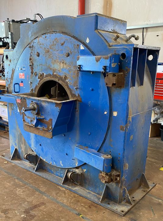
Chipper unit prior to Rotec overhaul
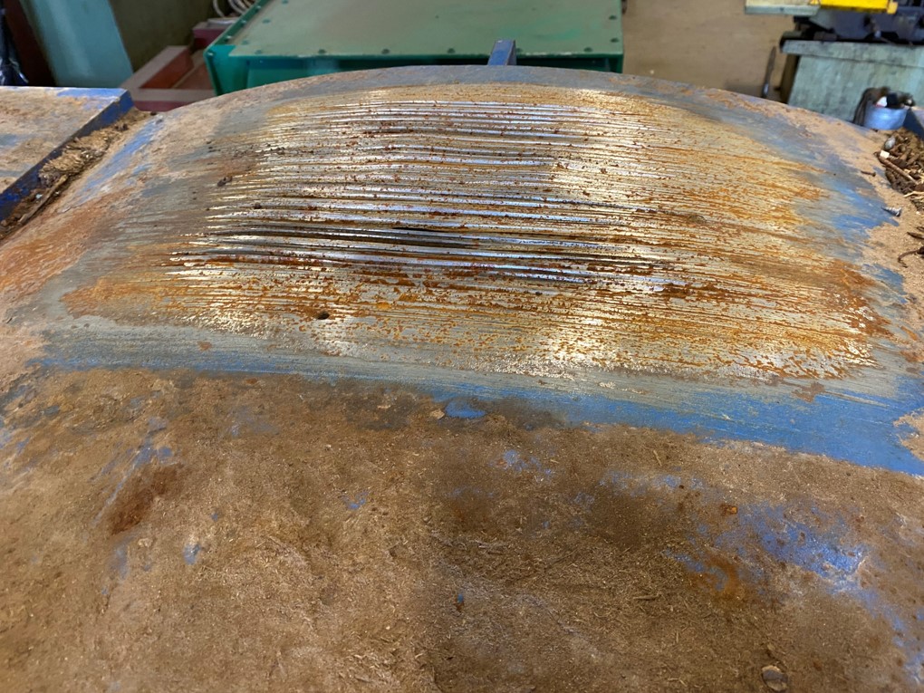
Damage caused by external conveyor belt
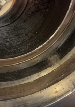
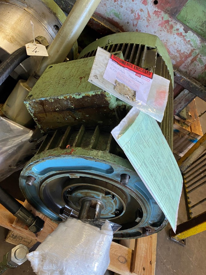
Damage to internal shaft
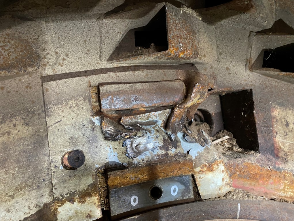
Internal damage caused during failure of blades
Modifications to front lower section to allow for outer adjustment on longer support sections, manufactured and fitted support bars
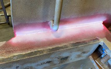
Die penetration checks on welding
Special support structure manufactured for accurate machining of the rear ring support pads
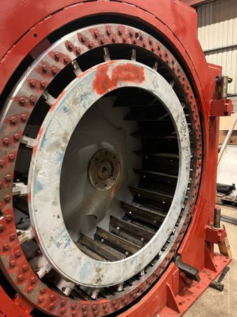
Inner bladed impellor fitted and clocked to ensure true
Outer door refitted on chipper
")


