How to prevent hydraulic oil overheating

Overheating is the second most common issue that occurs in hydraulic systems, behind leakages. Overheating of hydraulic systems is caused by inefficiencies which have resulted in loss of input power being converted to heat. To achieve stable fluid temperature, a hydraulic system’s capacity to dissipate heat must exceed its heat load. Overheating can be avoided by a reduction in hydraulic oil heat load and/or increasing heat dissipation.

Why reduce oil temperature?

Hydraulic fluid temperatures above 82°C (180°F) is likely to lead to oil degradation and cause damage to hydraulic seal compounds. While the operation of any hydraulic system at temperatures above 82°C should be avoided, fluid temperature is too high when viscosity falls below the optimum value for the hydraulic system’s components. This can occur well below 82°C, depending on the fluid’s viscosity grade (weight). To achieve a stable oil temperature, the hydraulic system must be able to dissipate heat faster than it is built up.

Heat dissipation

Heat dissipation occurs in the hydraulic reservoir. Regularly check there are no obstructions to the air flow into the reservoir and that fluid levels are correct.

Heat exchangers

Similarly to the reservoir checks, ensure the core of heat exchangers are not obstructed. Heat exchangers rely on flow-rate, hydraulic oil temperature and coolant in order to disperse heat suitably. It is vital that faulty cooling circuits are replaced. Infra-red thermometers are a reliable way to measure the performance and oil flow rate of heat exchangers.

Oil pressure and leakage

Reduction in system pressure or oil leakage will cause increased heat generation. It is critical that the cause of the leaking is identified and then rectified appropriately. If a relief valve is underneath or positioned too closely to the pressure setting of a pressure-compensator in a closed-centre circuit, it may lead to increased heat generation and the system pressure cannot reach the pressure compensator setting. Subsequently, the component will continue to move oil thorough the system, passing over the relief valve, which produces heat.

Ensuring effective hydraulic oil analysis

Reports suggest around 80% of all hydraulic failures are thought to be caused by fluid contamination* making regular, effective oil analysis a top priority for any business working with hydraulics.

Hydraulic component contamination is unwanted, foreign matter found within hydraulic fluid. Occasionally contamination is easy to spot. However, most of the time contamination is not visible to the human eye. Regardless of whether the contamination is visible or not, contamination has the potential to severely damage hydraulic components and systems.

Different types of hydraulic contamination

Contamination may be classified as abrasive or non-abrasive. Abrasive contamination involves particles that enter the hydraulic system, for example small paint flakes falling into the system during routine servicing, or a few grains of core sand left over from casting. Non-abrasive contaminants can be just as damaging and include particles, such as the remnants of shredded elastomeric seals from a pump, or chemicals, such as the by-products resulting from the oxidation of the oil or the result of reactions involving additives. While not abrasive, these contaminants can still have an extremely negative impact on the hydraulic performance of motors and pumps.

Some experts classify hydraulic contamination in three ways: gaseous, liquid or solid. Gaseous contamination negatively alters lubricating properties of a hydraulic system, creating wear and thus increasing the risk of further contamination. Liquid contamination also impacts lubricating capabilities as well as causing rust. Solid contamination can be responsible for valve blockages, substantial pump damage and blown seals and gaskets.

Recognizing the Sources of Fluid Contamination

Brand new fluid can be contaminated. Fluid contamination can occur during the manufacturing of the hydraulic oil, therefore before adding any power fluid to a hydraulic system or component (including reservoirs, pumps, valves or motors) it should be carefully filtered through a fluid servicing cart/unit. Be aware that contamination can also happen when fluid is being transferred or added to a hydraulic system.

Even new equipment and components can be contaminated. Whether it’s a new equipment or components, contamination may already have occurred either during the manufacture or assembly of the product. Smears of grease, tiny particles of weld spatter, or a thread from a rag have all been found to pollute brand new hydraulic systems and components.

During normal operation, some contamination will form. This includes non-abrasive chemical contamination caused by chemical reactions being triggered as the hydraulic fluid ages or is exposed to higher temperatures than originally recommended. Further, abrasive contamination can occur due to physical damage to hydraulic components, such as the rotating group in a hydraulic motor or failed bearings in a hydraulic pump – all of which is potentially catastrophic to hydraulic systems.

Testing Hydraulic Fluid Contamination

For hydraulic equipment to remain in good order, it should be regularly tested for contamination according to the manufacturer’s recommendation. Additionally, contamination checks should be carried out whenever contamination is suspected, or when the system has been operating at unusually high temperatures. A thorough contamination check involves taking more than one sample of the hydraulic fluid in different locations (for example the fluid reservoir and other locations), allowing you to track down the source of the contamination. Identifying and addressing the cause of the hydraulic fluid contamination is crucial to prevent the inevitable breakdown and increased repair costs.

Preventing Hydraulic Contamination

Filtering is essential to prevent hydraulic contamination. All fluid should be filtered through a fluid service cart or unit before it is transferred to a hydraulic system and/or components. Filters should be checked, cleaned, and replaced per manufacturer guidelines. We advise using those recommended by the manufacturer and to avoid cheap, low-quality filters. Filters should only be removed from their packaging, in a clean environment, immediately before use and handled carefully to reduce the risk of contamination.

Take samples before flushing original fluid and again when adding the new fluid. Remember to also change filters. Depending on the results from the samples, filters and fluids may need more often.

Another way to prevent hydraulic fluid contamination is by keeping a clean work environment. Only lint-free cloths should be used and workbenches, tools and servicing equipment kept clean to minimise the risk of contamination. Whenever disconnecting hydraulic fittings or lines, the workspace and all components should be cleaned in an approved dry solvent, dried (with a lint-free cloth, as needed), and then lubricated before assembly takes place. Always use dust caps on the ends of couplings when they are not in use.

Hydraulic Oil Analysis with Rotec Hydraulics Ltd

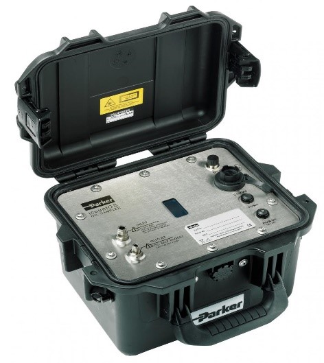
As well as offering an expert maintenance, repair and overhaul service, Rotec Hydraulics Ltd is proud to offer the Parker icount Oil Sampler (IOS) – a portable condition monitoring for hydraulic oil and fuel systems.

IOS is an innovative solution to measuring the quality of hydraulic oils and hydrocarbon fuels. Lightweight, robust and portable, IOS features a laser detection particle counter, battery and pump plus memory with web page generator for data download onto any PC or laptop – enabling clients to sample oil on-site and gather results within 5minutes. The IOS’s ability to sample directly from a hydraulic reservoir, barrel, vehicle fuel tank or from a high pressure online hydraulic system with the addition of a pressure reducing adaptor makes it undoubtedly the most adaptable contamination service tool available today. Contact us today for more information.


*Khalil, M.K.B. (2019) “Hydraulic Fluids and Contamination Control”, avaliable online at https://www.researchgate.net/publication/332158093_Hydraulic_Fluids_and_Contamination_Control

Custom made hydraulic winch system for the utilities sector

Rotec Hydraulics Ltd has recently completed works on a custom made hydraulic winch system for the utilities market.

Fitted to a fleet of Ford Ranger vehicles, these bespoke winches have been designed, built, installed and tested by our in-house team of engineers and include a hydraulic system, electronic control system and mechanical components.

The Capstan winch is specifically designed for fast line speeds and has a 350Kg working load limit with a remote electrical foot pedal operation

Safety features include an integral fail safe static brake and integral dynamic braking.

The Capstan winch drum is made of stainless steel and the winch is deployed on a sliding system to allow the operator to move it from stored position to operational position easily.

Our client is one of the world’s largest publicly listed utilities focused on transmission and distribution of electricity and gas. They play a vital role in connecting millions of people to the energy they use safely, reliably and efficiently. Rotec has worked with this organisation for several years and are proud of the strong, effective relationship we share.

At Rotec the team work on many different projects.  Much of the work undertaken requires the integration of knowledge and skills from across the Rotec team, to deliver all of the elements that make up a client brief. For more information on the services we offer, please click here.


Custom Designed Winching Systems

Isuzu Dmax

Rotec have been working with the Utility market for the last 20 years – designing and manufacturing winch systems for overhead line teams throughout the UK. Traditional vehicles such as landrovers were deemed the work horse and industry standard. Working with a number of organisation the challenge to replace the landrover centred on certain replacement vehicles – such as the Isuzu DMAX.

The bespoke system includes the following:

  • Electro-hydraulic PTO (Power Take Off) for the pump
  • Custom designed hydraulic manifold assembly, which uses an electronic proportional directional control valve
  • Dual pressure control which allows for pressure selection
  • Custom made hydraulic reservoir
  • Custom electronic control system, including a remote pendant with joystick control as well as a 2nd joystick located in the cab
  • Integrated electronic hand throttle for the engine
  • Quality winch and Parker hydraulic hose supplied with pressure test certification which can be traced throughout the Parker network using PTS system

The system operates in two work modes:

  • Lifting mode: capable of lifting up to 1550 Kg (SWL)
  • Self – recovery: capable of pulling 3600 Kg

The bespoke system is designed and manufactured completely in-house, fully – tested prior to despatch.

Grain ship-loader replacement electro-hydraulic control system

Thanks to the working relationship spanning many years, Rotec were invited to quote for the replacement of the hydraulic power unit and controls of the grain/feed products ship loader travelling gantry system. The client was faced with reliability and obsolescence issues with the original equipment dating back to the 1980s. It is the only plant capable of this function at the port and is in use constantly.

The ship loader hydraulic functions consist of a dual pumping system and associated hydraulic equipment built into an up-cycled twenty-foot shipping container. The container sits on the machine approximately 20 metres above dock level, which presented some unique access issues.

 Based on the original system design, Rotec designed and manufactured a complete self-contained hydraulic system and associated dedicated electrical control panels which control vertical and horizontal movements of the grain conveyors and loading chute to align over the vessel’s holds as required.

The container was specially modified to accept and fit the hydraulic system. This included full sound and fireproofing, internal full bunding and bespoke flooring and ventilation integration. The hydraulic system consists of a primary pump system driven by a 100KW 3300VAC electric motor and proportionally controlled variable displacement pump with a completely redundant secondary backup system in case of partial or total power loss. This 400VAC backup system is supplied from an external generator and is used to recover the chute off a vessel during a power loss when necessary. The main pump systems are supported by cooling and filtration systems and associated electrical control and monitoring equipment which in turn all interface and interlock to the main ship loader external control system.

21The project initially began in 2017, but project was temporarily halted by Brexit and later on, the outbreak of COVID-19. However, following a major fire one evening whilst in use on a vessel which completely destroyed the old containerised system, surrounding cabling and pipework, the project objectives and target completion date was rapidly brought forward to minimize the client’s downtime.

Due to our very flexible approach and ability to respond to an everchanging priorities list, Rotec was able to pick up and resume the build process quickly and managed to complete and factory test the unit ready for site delivery and install by the end of May. Our on-site engineers in the meantime stripped out and replaced large quantities of fire damaged external fixed stainless and special alloy tubing and replaced all external flexible hoses on the machine. The container unit and system were craned into place, pipework connections completed then flushed thoroughly. The system has now finished its commissioning and setting to work process, on time and on budget, and is ready to serve the port for this vital service for at least another 30 years minimum. The client is completely satisfied with the product and service received by him by our team of design, manufacturing, and field service personnel.


Portable Flushing Units

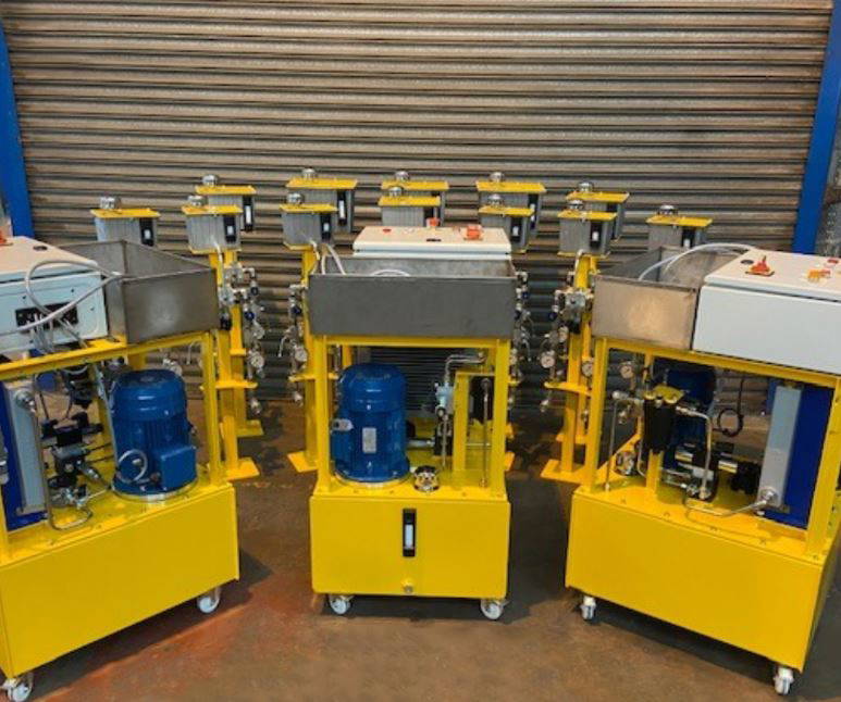
The Rotec Portable Flushing Unit performs a function that’s important for any hydraulic system: It flushes out and filters build-up of contaminants, leaving the system ready for use in minutes. It is crucial for maintenance, extends system lifetime, helps avoid repair costs and downtime. The unit can also be adjusted for fuel filtration and can be used for filling the system (filtering all the while).

This versatile unit is built into a trolley frame which makes it easily manoeuvrable and can often be found on keysides, decks or factory floors. The flushing unit is suitable for use in a variety of applications, including but not limited to: marine, industrial & off-shore.

The system is bespoke and can be tailored to your needs for use with a range of water-based control fluids or hydraulic mineral oils.

Technical Information of the system pictured:

  • Use: localised flushing on marine applications
  • Filtration: 10Q micron
  • Motor: 1.5Kw, 110v
  • Flow: 20 l/min
  • Pressure: up to 28 bar
  • Supplied with 5 metre suction and delivery hoses