A basic guide to hydraulic oil

Hydraulic oil is a non-compressible fluid that is used to transfer power within hydraulic machinery and equipment, and lubricates system components. It is crucially important to regularly check and maintain a system’s hydraulic fluid.

Hydraulic oil can be synthetic or mineral based. Other chemical additives are often added to hydraulic fluid to maintain or improve performance of the oil and the equipment within the hydraulic system. The additives can help to prevent corrosion, rusting and water contamination. It is critical the appropriate oil is chosen for each system. Using the incorrect oil can lead to performance issues and potentially system and component damage.

Additives may include anti-freeze for oils that are been used in harsh, cold environments. In the event of high temperatures, which in turn would lower the oil’s viscosity and increase the risk of leakages, additives may be added to maintain a suitable viscosity for the system being used.

If hydraulic fluid is being used in a high pressure condition, heavy-duty oil is necessary. Heavy-duty hydraulic oil often contains additives that prevent wear.

Biodegradable and environmentally-friendly oils are excellent for those working in sectors that may pose a potential risk of oil spills or leak, and thus environmental contamination. The oils, which are made of rapeseed and other vegetable oils, are also great for businesses with sustainability awareness and targets.

Hydraulic oil life

It’s important to maintain healthy hydraulic systems and components, a crucial part of this is looking after your hydraulic oil.

Modern hydraulic systems are typically smaller and use less oil during operation. Pumps can also produce a lot more output, subsequently producing higher pressures. Less oil means higher fluid temperatures – which in turn, increases oxidation and thermal stress on the additives on the oil. 

Several factors can influence hydraulic oil longevity including:

  • Oil quality
  • Working conditions
  • Oil temperature
  • Oxidation
  • Contamination.

Within the right environment and with the correct maintenance, a high quality oil may last longer than six months. 

For technical support and more information about choosing and maintaining hydraulic oil for your systems, contact Rotec via sales@rotec.net or phone 01823 348900. 

A guide to hydraulic motors

Axial piston, radial piston, hydraulic gear or hydraulic vane – there are numerous types of hydraulic motors.

When operated, a hydraulic motor uses hydraulic pressure to rotate. Power fluid enters the hydraulic motor, turning the shaft. The volume of oil supplied by the pump determines the velocity of the motor. Thus, the torque generated is dependent on the amount of supplied pressure.

Axial piston motors

Axial piston motors use a bent axis design or a swash plate principle. The fixed displacement type works as a hydraulic motor and can be used in open and closed circuits. In contrast to this, the variable displacement type operates like a hydraulic pump.

In the bent axis design, pistons move to and fro within the cylinder block bores. This movement is converted into rotary movement via the piston ball joint at the driving flange. In the swash plate design, pistons move to and fro in the cylinder block. Subsequently it revolves and turns the drive shaft via the connected cotter pin.

Radial piston motors

Highly efficient and usually long-lasting, radial piston motors provide excellent low speed operation with high efficiency and generate high torque at relatively low shaft speeds. Referred to as LSHT – Low Speed High Torque motors, the low output speed means in some cases a gearbox is not required.

Radial piston motors are commonly found in: excavators, cranes, ground drilling equipment, winch drives, concrete mixers, trawlers and plastic injection moulding machines. Generally, there are two basic types of radial piston motors – crankshaft radial piston motor and multilobe cam ring design. Other types of radial piston motors include compact radial piston motors, dual displacement radial piston motors and fixed displacement radial piston motors.

Hydraulic gear motors

A hydraulic gear motor consists of two gears: the driven gear (attached to the output shaft by way of a key) and the idler gear. High pressure oil is ported into one side of the gears, where it flows around the periphery of the gears, between the gear tips and the wall housing, to the outlet port. The gears then mesh, not allowing the oil from the outlet side to flow back to the inlet side.

For lubrication, the gear motor uses a small amount of oil from the pressurized side of the gears, bleeds this through the (typically) hydrodynamic bearings, and vents the same oil either to the low pressure side of the gears, or through a dedicated drain port on the motor housing.

One very important gear motor feature is that catastrophic breakdown is a lot less common than in most other types of hydraulic motors. This is because the gears gradually wear down the housing and/or main bushings, gradually reducing the volumetric efficiency of the motor. The gear motor can degrade to the point of near uselessness. This often happens long before wear causes the unit to seize or break down.

Hydraulic vane motors

Hydraulic vane motors are used in both industrial and mobile applications. For example, screw-drive, injection moulding and agricultural machinery. These motors tend to have less internal leaking than a gear motor. And subsequently, they are better to use in applications requiring lower speeds.

Hydraulic vane motors feature reduced noise level, low flow pulsation, high torque at low speeds and a simple design. Moreover they are easy to service and suitable for vertical installation. To function correctly, the rotor vanes must be pressed against the inside of the motor housing. This can be done through spiral or leaf springs, but rods are also suitable.

A vane motor typically features a displacement volume between 9 cc/rev to 214 cc/rev and a maximum 230 bar pressure. The speeds range from 100 to 2,500 rpm. Maximum torque of up to 650 Nm.

For technical support and more information on hydraulic motors, contact the Rotec sales team via sales@rotec.net or phone 01823 348900.

To browse our hydraulic motor products, visit https://rotec-catalogue.co.uk/hydraulics/components.

How to prevent hydraulic oil overheating

Overheating is the second most common issue that occurs in hydraulic systems, behind leakages. Overheating of hydraulic systems is caused by inefficiencies which have resulted in loss of input power being converted to heat. To achieve stable fluid temperature, a hydraulic system’s capacity to dissipate heat must exceed its heat load. Overheating can be avoided by a reduction in hydraulic oil heat load and/or increasing heat dissipation.

Why reduce oil temperature?

Hydraulic fluid temperatures above 82°C (180°F) is likely to lead to oil degradation and cause damage to hydraulic seal compounds. While the operation of any hydraulic system at temperatures above 82°C should be avoided, fluid temperature is too high when viscosity falls below the optimum value for the hydraulic system’s components. This can occur well below 82°C, depending on the fluid’s viscosity grade (weight). To achieve a stable oil temperature, the hydraulic system must be able to dissipate heat faster than it is built up.

Heat dissipation

Heat dissipation occurs in the hydraulic reservoir. Regularly check there are no obstructions to the air flow into the reservoir and that fluid levels are correct.

Heat exchangers

Similarly to the reservoir checks, ensure the core of heat exchangers are not obstructed. Heat exchangers rely on flow-rate, hydraulic oil temperature and coolant in order to disperse heat suitably. It is vital that faulty cooling circuits are replaced. Infra-red thermometers are a reliable way to measure the performance and oil flow rate of heat exchangers.

Oil pressure and leakage

Reduction in system pressure or oil leakage will cause increased heat generation. It is critical that the cause of the leaking is identified and then rectified appropriately. If a relief valve is underneath or positioned too closely to the pressure setting of a pressure-compensator in a closed-centre circuit, it may lead to increased heat generation and the system pressure cannot reach the pressure compensator setting. Subsequently, the component will continue to move oil thorough the system, passing over the relief valve, which produces heat.

Ensuring effective hydraulic oil analysis

Reports suggest around 80% of all hydraulic failures are thought to be caused by fluid contamination* making regular, effective oil analysis a top priority for any business working with hydraulics.

Hydraulic component contamination is unwanted, foreign matter found within hydraulic fluid. Occasionally contamination is easy to spot. However, most of the time contamination is not visible to the human eye. Regardless of whether the contamination is visible or not, contamination has the potential to severely damage hydraulic components and systems.

Different types of hydraulic contamination

Contamination may be classified as abrasive or non-abrasive. Abrasive contamination involves particles that enter the hydraulic system, for example small paint flakes falling into the system during routine servicing, or a few grains of core sand left over from casting. Non-abrasive contaminants can be just as damaging and include particles, such as the remnants of shredded elastomeric seals from a pump, or chemicals, such as the by-products resulting from the oxidation of the oil or the result of reactions involving additives. While not abrasive, these contaminants can still have an extremely negative impact on the hydraulic performance of motors and pumps.

Some experts classify hydraulic contamination in three ways: gaseous, liquid or solid. Gaseous contamination negatively alters lubricating properties of a hydraulic system, creating wear and thus increasing the risk of further contamination. Liquid contamination also impacts lubricating capabilities as well as causing rust. Solid contamination can be responsible for valve blockages, substantial pump damage and blown seals and gaskets.

Recognizing the Sources of Fluid Contamination

Brand new fluid can be contaminated. Fluid contamination can occur during the manufacturing of the hydraulic oil, therefore before adding any power fluid to a hydraulic system or component (including reservoirs, pumps, valves or motors) it should be carefully filtered through a fluid servicing cart/unit. Be aware that contamination can also happen when fluid is being transferred or added to a hydraulic system.

Even new equipment and components can be contaminated. Whether it’s a new equipment or components, contamination may already have occurred either during the manufacture or assembly of the product. Smears of grease, tiny particles of weld spatter, or a thread from a rag have all been found to pollute brand new hydraulic systems and components.

During normal operation, some contamination will form. This includes non-abrasive chemical contamination caused by chemical reactions being triggered as the hydraulic fluid ages or is exposed to higher temperatures than originally recommended. Further, abrasive contamination can occur due to physical damage to hydraulic components, such as the rotating group in a hydraulic motor or failed bearings in a hydraulic pump – all of which is potentially catastrophic to hydraulic systems.

Testing Hydraulic Fluid Contamination

For hydraulic equipment to remain in good order, it should be regularly tested for contamination according to the manufacturer’s recommendation. Additionally, contamination checks should be carried out whenever contamination is suspected, or when the system has been operating at unusually high temperatures. A thorough contamination check involves taking more than one sample of the hydraulic fluid in different locations (for example the fluid reservoir and other locations), allowing you to track down the source of the contamination. Identifying and addressing the cause of the hydraulic fluid contamination is crucial to prevent the inevitable breakdown and increased repair costs.

Preventing Hydraulic Contamination

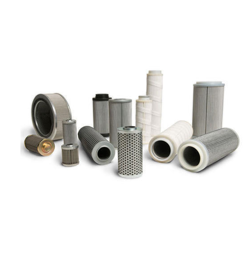
Filtering is essential to prevent hydraulic contamination. All fluid should be filtered through a fluid service cart or unit before it is transferred to a hydraulic system and/or components. Filters should be checked, cleaned, and replaced per manufacturer guidelines. We advise using those recommended by the manufacturer and to avoid cheap, low-quality filters. Filters should only be removed from their packaging, in a clean environment, immediately before use and handled carefully to reduce the risk of contamination.

Take samples before flushing original fluid and again when adding the new fluid. Remember to also change filters. Depending on the results from the samples, filters and fluids may need more often.

Another way to prevent hydraulic fluid contamination is by keeping a clean work environment. Only lint-free cloths should be used and workbenches, tools and servicing equipment kept clean to minimise the risk of contamination. Whenever disconnecting hydraulic fittings or lines, the workspace and all components should be cleaned in an approved dry solvent, dried (with a lint-free cloth, as needed), and then lubricated before assembly takes place. Always use dust caps on the ends of couplings when they are not in use.

Hydraulic Oil Analysis with Rotec Hydraulics Ltd

As well as offering an expert maintenance, repair and overhaul service, Rotec Hydraulics Ltd is proud to offer the Parker icount Oil Sampler (IOS) – a portable condition monitoring for hydraulic oil and fuel systems.

IOS is an innovative solution to measuring the quality of hydraulic oils and hydrocarbon fuels. Lightweight, robust and portable, IOS features a laser detection particle counter, battery and pump plus memory with web page generator for data download onto any PC or laptop – enabling clients to sample oil on-site and gather results within 5minutes. The IOS’s ability to sample directly from a hydraulic reservoir, barrel, vehicle fuel tank or from a high pressure online hydraulic system with the addition of a pressure reducing adaptor makes it undoubtedly the most adaptable contamination service tool available today. Contact us today for more information.


*Khalil, M.K.B. (2019) “Hydraulic Fluids and Contamination Control”, avaliable online at https://www.researchgate.net/publication/332158093_Hydraulic_Fluids_and_Contamination_Control

Custom made hydraulic winch system for the utilities sector

Rotec Hydraulics Ltd has recently completed works on a custom made hydraulic winch system for the utilities market.

Fitted to a fleet of Ford Ranger vehicles, these bespoke winches have been designed, built, installed and tested by our in-house team of engineers and include a hydraulic system, electronic control system and mechanical components.

The Capstan winch is specifically designed for fast line speeds and has a 350Kg working load limit with a remote electrical foot pedal operation

Safety features include an integral fail safe static brake and integral dynamic braking.

The Capstan winch drum is made of stainless steel and the winch is deployed on a sliding system to allow the operator to move it from stored position to operational position easily.

Our client is one of the world’s largest publicly listed utilities focused on transmission and distribution of electricity and gas. They play a vital role in connecting millions of people to the energy they use safely, reliably and efficiently. Rotec has worked with this organisation for several years and are proud of the strong, effective relationship we share.

At Rotec the team work on many different projects.  Much of the work undertaken requires the integration of knowledge and skills from across the Rotec team, to deliver all of the elements that make up a client brief. For more information on the services we offer, please click here.


Custom Designed Winching Systems

Isuzu Dmax

Rotec have been working with the Utility market for the last 20 years – designing and manufacturing winch systems for overhead line teams throughout the UK. Traditional vehicles such as landrovers were deemed the work horse and industry standard. Working with a number of organisation the challenge to replace the landrover centred on certain replacement vehicles – such as the Isuzu DMAX.

The bespoke system includes the following:

  • Electro-hydraulic PTO (Power Take Off) for the pump
  • Custom designed hydraulic manifold assembly, which uses an electronic proportional directional control valve
  • Dual pressure control which allows for pressure selection
  • Custom made hydraulic reservoir
  • Custom electronic control system, including a remote pendant with joystick control as well as a 2nd joystick located in the cab
  • Integrated electronic hand throttle for the engine
  • Quality winch and Parker hydraulic hose supplied with pressure test certification which can be traced throughout the Parker network using PTS system

The system operates in two work modes:

  • Lifting mode: capable of lifting up to 1550 Kg (SWL)
  • Self – recovery: capable of pulling 3600 Kg

The bespoke system is designed and manufactured completely in-house, fully – tested prior to despatch.