A guide to hydraulic motors

Axial piston, radial piston, hydraulic gear or hydraulic vane – there are numerous types of hydraulic motors.

When operated, a hydraulic motor uses hydraulic pressure to rotate. Power fluid enters the hydraulic motor, turning the shaft. The volume of oil supplied by the pump determines the velocity of the motor. Thus, the torque generated is dependent on the amount of supplied pressure.

Axial piston motors

Axial piston motors use a bent axis design or a swash plate principle. The fixed displacement type works as a hydraulic motor and can be used in open and closed circuits. In contrast to this, the variable displacement type operates like a hydraulic pump.

In the bent axis design, pistons move to and fro within the cylinder block bores. This movement is converted into rotary movement via the piston ball joint at the driving flange. In the swash plate design, pistons move to and fro in the cylinder block. Subsequently it revolves and turns the drive shaft via the connected cotter pin.

Radial piston motors

Highly efficient and usually long-lasting, radial piston motors provide excellent low speed operation with high efficiency and generate high torque at relatively low shaft speeds. Referred to as LSHT – Low Speed High Torque motors, the low output speed means in some cases a gearbox is not required.

Radial piston motors are commonly found in: excavators, cranes, ground drilling equipment, winch drives, concrete mixers, trawlers and plastic injection moulding machines. Generally, there are two basic types of radial piston motors – crankshaft radial piston motor and multilobe cam ring design. Other types of radial piston motors include compact radial piston motors, dual displacement radial piston motors and fixed displacement radial piston motors.

Hydraulic gear motors

A hydraulic gear motor consists of two gears: the driven gear (attached to the output shaft by way of a key) and the idler gear. High pressure oil is ported into one side of the gears, where it flows around the periphery of the gears, between the gear tips and the wall housing, to the outlet port. The gears then mesh, not allowing the oil from the outlet side to flow back to the inlet side.

For lubrication, the gear motor uses a small amount of oil from the pressurized side of the gears, bleeds this through the (typically) hydrodynamic bearings, and vents the same oil either to the low pressure side of the gears, or through a dedicated drain port on the motor housing.

One very important gear motor feature is that catastrophic breakdown is a lot less common than in most other types of hydraulic motors. This is because the gears gradually wear down the housing and/or main bushings, gradually reducing the volumetric efficiency of the motor. The gear motor can degrade to the point of near uselessness. This often happens long before wear causes the unit to seize or break down.

Hydraulic vane motors

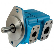
Hydraulic vane motors are used in both industrial and mobile applications. For example, screw-drive, injection moulding and agricultural machinery. These motors tend to have less internal leaking than a gear motor. And subsequently, they are better to use in applications requiring lower speeds.

Hydraulic vane motors feature reduced noise level, low flow pulsation, high torque at low speeds and a simple design. Moreover they are easy to service and suitable for vertical installation. To function correctly, the rotor vanes must be pressed against the inside of the motor housing. This can be done through spiral or leaf springs, but rods are also suitable.

A vane motor typically features a displacement volume between 9 cc/rev to 214 cc/rev and a maximum 230 bar pressure. The speeds range from 100 to 2,500 rpm. Maximum torque of up to 650 Nm.

For technical support and more information on hydraulic motors, contact the Rotec sales team via sales@rotec.net or phone 01823 348900.

To browse our hydraulic motor products, visit https://rotec-catalogue.co.uk/hydraulics/components.

Rotec provides IoT technology for smart monitoring

Internet of Things (IoT) technology enables engineers to remotely control and monitor various performance and safety parameters using strategically placed, wireless sensors to provide data and control systems over the internet.

IoT technology can lead to a reduction in downtime, better response rates and speed of intervention for predictive maintenance.

Everyday examples of IoT include smart home security systems or wearable health monitors. In terms of engineering, the potential for IoT is staggering, from autonomous agricultural equipment to advanced monitoring systems allowing machinery to be monitored from any location worldwide.

With more than 7 billion connected IoT devices today, experts are expecting this number to grow to 10 billion by 2020 and 22 billion by 2025.

Rotec has invested in IoT devices to offer this forethinking technology to our new and existing customers, as part of the business’s strategy to maximise the use of the latest technology, data analysis and to find environmentally sustainable solutions for our customers. We are now the only company South of England to be offering a range of Parker IoT products suited to all sector markets that rely on hydraulic, pneumatic and electrical mechanical engineering solutions. 

This data centric and digital approach enhances both our own and our clients’ understanding of what really ‘works’ when designing hydraulics, pneumatics and electrical mechanical systems. It complements the other services delivered by of our brand such as bespoke design, custom builds, maintenance, repair and overhaul activities.

IoT can be applied to all sectors. Examples include IOS; an innovative solution to measuring the quality of hydraulic oils and hydrocarbon fuels. Lightweight, robust and portable, IOS features a laser detection particle counter, battery and pump plus memory with web page generator for data download onto any PC or laptop – enabling clients to sample oil on-site and gather results within 2minutes. The IOS’s ability to sample directly from a hydraulic reservoir, barrel, vehicle fuel tank or from a high pressure online hydraulic system with the addition of a pressure reducing adaptor makes it undoubtedly the most adaptable contamination service tool available today. 

Another Parker IoT product range Rotec are proud to offer is an extension to the IQAN mobile controller family of hardware; products we have very extensive experience and knowledge of . This product range permits clients to quickly write applications for the desired functionality of their machine, reducing programming time and expense for machine control systems.

We are currently researching and designing a custom-made, cutting-edge hydraulic system, with IoT for remote monitoring embedded into the design, for a prominent name within the UK marine industry. Using Rotec designed test case fitted with Parker IQAN and GPS hardware, our client will have the technology to remotely dial in to monitor the hydraulic system sensors. This ability to proactively monitor remotely has numerous benefits, including reducing severity of damages caused by contamination and temperature, as well as reducing downtime for non-remote monitoring activities.

To discuss your requirements, and speak to a member of our team about IoT, please contact sales@rotec.net or call 01823 348900.

How to prevent hydraulic oil overheating

Overheating is the second most common issue that occurs in hydraulic systems, behind leakages. Overheating of hydraulic systems is caused by inefficiencies which have resulted in loss of input power being converted to heat. To achieve stable fluid temperature, a hydraulic system’s capacity to dissipate heat must exceed its heat load. Overheating can be avoided by a reduction in hydraulic oil heat load and/or increasing heat dissipation.

Why reduce oil temperature?

Hydraulic fluid temperatures above 82°C (180°F) is likely to lead to oil degradation and cause damage to hydraulic seal compounds. While the operation of any hydraulic system at temperatures above 82°C should be avoided, fluid temperature is too high when viscosity falls below the optimum value for the hydraulic system’s components. This can occur well below 82°C, depending on the fluid’s viscosity grade (weight). To achieve a stable oil temperature, the hydraulic system must be able to dissipate heat faster than it is built up.

Heat dissipation

Heat dissipation occurs in the hydraulic reservoir. Regularly check there are no obstructions to the air flow into the reservoir and that fluid levels are correct.

Heat exchangers

Similarly to the reservoir checks, ensure the core of heat exchangers are not obstructed. Heat exchangers rely on flow-rate, hydraulic oil temperature and coolant in order to disperse heat suitably. It is vital that faulty cooling circuits are replaced. Infra-red thermometers are a reliable way to measure the performance and oil flow rate of heat exchangers.

Oil pressure and leakage

Reduction in system pressure or oil leakage will cause increased heat generation. It is critical that the cause of the leaking is identified and then rectified appropriately. If a relief valve is underneath or positioned too closely to the pressure setting of a pressure-compensator in a closed-centre circuit, it may lead to increased heat generation and the system pressure cannot reach the pressure compensator setting. Subsequently, the component will continue to move oil thorough the system, passing over the relief valve, which produces heat.

Ensuring effective hydraulic oil analysis

Reports suggest around 80% of all hydraulic failures are thought to be caused by fluid contamination* making regular, effective oil analysis a top priority for any business working with hydraulics.

Hydraulic component contamination is unwanted, foreign matter found within hydraulic fluid. Occasionally contamination is easy to spot. However, most of the time contamination is not visible to the human eye. Regardless of whether the contamination is visible or not, contamination has the potential to severely damage hydraulic components and systems.

Different types of hydraulic contamination

Contamination may be classified as abrasive or non-abrasive. Abrasive contamination involves particles that enter the hydraulic system, for example small paint flakes falling into the system during routine servicing, or a few grains of core sand left over from casting. Non-abrasive contaminants can be just as damaging and include particles, such as the remnants of shredded elastomeric seals from a pump, or chemicals, such as the by-products resulting from the oxidation of the oil or the result of reactions involving additives. While not abrasive, these contaminants can still have an extremely negative impact on the hydraulic performance of motors and pumps.

Some experts classify hydraulic contamination in three ways: gaseous, liquid or solid. Gaseous contamination negatively alters lubricating properties of a hydraulic system, creating wear and thus increasing the risk of further contamination. Liquid contamination also impacts lubricating capabilities as well as causing rust. Solid contamination can be responsible for valve blockages, substantial pump damage and blown seals and gaskets.

Recognizing the Sources of Fluid Contamination

Brand new fluid can be contaminated. Fluid contamination can occur during the manufacturing of the hydraulic oil, therefore before adding any power fluid to a hydraulic system or component (including reservoirs, pumps, valves or motors) it should be carefully filtered through a fluid servicing cart/unit. Be aware that contamination can also happen when fluid is being transferred or added to a hydraulic system.

Even new equipment and components can be contaminated. Whether it’s a new equipment or components, contamination may already have occurred either during the manufacture or assembly of the product. Smears of grease, tiny particles of weld spatter, or a thread from a rag have all been found to pollute brand new hydraulic systems and components.

During normal operation, some contamination will form. This includes non-abrasive chemical contamination caused by chemical reactions being triggered as the hydraulic fluid ages or is exposed to higher temperatures than originally recommended. Further, abrasive contamination can occur due to physical damage to hydraulic components, such as the rotating group in a hydraulic motor or failed bearings in a hydraulic pump – all of which is potentially catastrophic to hydraulic systems.

Testing Hydraulic Fluid Contamination

For hydraulic equipment to remain in good order, it should be regularly tested for contamination according to the manufacturer’s recommendation. Additionally, contamination checks should be carried out whenever contamination is suspected, or when the system has been operating at unusually high temperatures. A thorough contamination check involves taking more than one sample of the hydraulic fluid in different locations (for example the fluid reservoir and other locations), allowing you to track down the source of the contamination. Identifying and addressing the cause of the hydraulic fluid contamination is crucial to prevent the inevitable breakdown and increased repair costs.

Preventing Hydraulic Contamination

Filtering is essential to prevent hydraulic contamination. All fluid should be filtered through a fluid service cart or unit before it is transferred to a hydraulic system and/or components. Filters should be checked, cleaned, and replaced per manufacturer guidelines. We advise using those recommended by the manufacturer and to avoid cheap, low-quality filters. Filters should only be removed from their packaging, in a clean environment, immediately before use and handled carefully to reduce the risk of contamination.

Take samples before flushing original fluid and again when adding the new fluid. Remember to also change filters. Depending on the results from the samples, filters and fluids may need more often.

Another way to prevent hydraulic fluid contamination is by keeping a clean work environment. Only lint-free cloths should be used and workbenches, tools and servicing equipment kept clean to minimise the risk of contamination. Whenever disconnecting hydraulic fittings or lines, the workspace and all components should be cleaned in an approved dry solvent, dried (with a lint-free cloth, as needed), and then lubricated before assembly takes place. Always use dust caps on the ends of couplings when they are not in use.

Hydraulic Oil Analysis with Rotec Hydraulics Ltd

As well as offering an expert maintenance, repair and overhaul service, Rotec Hydraulics Ltd is proud to offer the Parker icount Oil Sampler (IOS) – a portable condition monitoring for hydraulic oil and fuel systems.

IOS is an innovative solution to measuring the quality of hydraulic oils and hydrocarbon fuels. Lightweight, robust and portable, IOS features a laser detection particle counter, battery and pump plus memory with web page generator for data download onto any PC or laptop – enabling clients to sample oil on-site and gather results within 5minutes. The IOS’s ability to sample directly from a hydraulic reservoir, barrel, vehicle fuel tank or from a high pressure online hydraulic system with the addition of a pressure reducing adaptor makes it undoubtedly the most adaptable contamination service tool available today. Contact us today for more information.


*Khalil, M.K.B. (2019) “Hydraulic Fluids and Contamination Control”, avaliable online at https://www.researchgate.net/publication/332158093_Hydraulic_Fluids_and_Contamination_Control

Charting the right course to efficiency in the marine industry

British Fluid Power Association recently published an article which collates testimonies from a number of BFPA member companies spokespeople, including Paul Prouse from Rotec Hydraulic Ltd. They consider some of the challenges associated with the effective use and maintenance of fluid power systems and related equipment within the marine sector.

One of the most challenging industry sectors for engineering sciences has to be marine, where technology must be designed and built to withstand the demanding conditions associated with the open seas. Therefore, within the fluid power and related systems and equipment industry, providers to the marine sector need to ensure their products are designed and built to be 100% fit for purpose.

Arguably the most glamorous market segment within the marine industry is superyachts. As many superyachts are based in warmer climes, such as the Mediterranean, the Caribbean or Dubai, the operation and maintenance of electro-hydraulic systems should be performed with equipment that can function effectively in very high temperatures.

Concept to design

Rotec Hydraulics Limited covers both commercial and pleasure applications. Rotec provides service and installation facilities to local and national fishing fleets, as well as operating systems for fuel, fire and hydraulic services fitted to luxury yachts.

Integrated systems

Integrated systems are the present and the future within the marine sector, according to Paul Prouse, Managing Director at RotecHydraulics Ltd. He maintains that the first challenge to providing the right system is obtaining a suitably detailed specification from customers of what kind of solution they are require for their specific system requirements and then matching these requirements to a practical solution that best suits the customer and the application. “There are now so many options electro-hydraulic/pneumatic products on the market which are constantly evolving,” said Prouse. “As the customer does not always know what is available it is up to us as design engineers to keep up to date with new products on the market and where they could be integrated if suitable.”

Prouse makes the point that an electro-hydraulic system that Rotec could fit on a superyacht would have to be compact, low maintenance and aesthetically pleasing whereas the same system fitted to a fishing boat would be rugged, industrial, easily maintainable and more cost sensitive. He adds that electro-hydraulics now offers a multitude of options that Rotec can then transpose to customers to give them system information, compact hydraulic systems, control interfaces and safety functionality.

Within the bespoke luxury yacht market, Paul Prouse makes the point that time from concept to design based on the budget can be difficult to predict as there can be many factors that increase design time over the original estimation. “Customers may have been working for much longer periods (months or years) on their design concept requirements, and when it comes to our part, timescales are often short in relation to the overall project timescales,” he said. “What could be classed as R&D work for bespoke projects is not always thought about or included in project costings and timescales, which adds pressure on designers to get it perfect first time.”

Rotec’s recent collaboration on the WaveAccess project was another example of a successful application of the use of hydraulics in a testing marine environment.

“Electronic control systems incorporating electronic valve control, electro-proportional valve control and actuator positioning feedback gives us a platform from where we can now control hydraulic actuators from a remote location without the need to be near to the hydraulic components,” he said.

Read more about the WaveAccess project: https://www.rotec.net/rotec-help-develop-groundbreaking-vessel-waveaccess/

The full BFPA article, including testimonials from other hydraulic companies available at:

https://bfpa.co.uk/news/charting-the-right-course-to-efficiency-in-the-marine-industry/

Author: Sarah Gardner, BFPA

Rotec part of a groundbreaking vessel development: WaveAccess

WaveAccess Tenacity vessel

In 2014, Rotec were invited to join Coastal Charters, a commercial maritime business based in West Cumbria, on the development of WaveAccess.

The project originally came as a response to an emerging trend within the offshore wind industry to move the construction further out into the sea.  The company anticipated the industry’s need for a reliable vessel that would be faster and able to cope with the challenging conditions further offshore.

The goal of the project was to design and build a rapid crew transfer vessel that would be faster, safer and cheaper to run than the vessels in use, resulting in the pilot vessel: Tenacity

The radical new design allows for transport of passengers and crew with dramatically reduced fuel consumption at twice the speed, while maintaining safety, minimising motion sickness and improving comfort at up to 40 kts in seas in excess of 2m. The vessel can be used for crew transfers in industries such as oil & gas, offshore wind and construction, search and rescue, patrol, medivac, safety boat, to name a few.

See video of the vessel in action on WaveAccess website or YouTube channel

WaveAccess Tenacity vessel

Thanks to  Rotec’s extensive marine experience and previous control systems the company had developed for use on multi-hull jet vessels in the wind-farm support vessel industry we were invited to participate in this innovative project.

Vessel interiorAndy Rimes, Rotec’s Technical Director outlines the project “Together with the team at WaveAccess and other specialists we developed a bespoke control system for the twin waterjet propulsion system to provide fully automated synchronised control of the jets, clutches, thrusters and main engines both in normal forward cruising modes and reverse facing tower operations.”

The electronic system is based on Parker Hannifin’s Iqan mobile controller and associated products. “As well as the electronic supervisory control and monitoring system we also completely re- equipped the Italian Castoldi waterjets hydraulic drive and control systems to provide fully proportional control electronically controlled from the Iqan system. This provides a smoother, more controllable and economic drive system. “


CGG Veritas Oceanic Sirius

All design work and bench testing took place at Rotec’s premises in Taunton, with the installation, setup and sea trials carried out by Rotec engineers at Coastal Charters home in Cumbria.

It was a challenging, yet ultimately rewarding, experience to be involved with the development of a concept vessel such as this and we wish Stephen and all the crew and team at WaveAccess best of luck with their promotion of the successful and innovative vessel to the industry.

For more information please visit: www.waveaccess.co.uk


Author: Sarka Humpolcova

Date: 06/04/2017