Rotec achieves Parker Certified Accumulator Service Centre recertification
100% Achilles audit _Rotec Hydraulics Ltd

Rotec is pleased to announce it has been re-certified as a Parker Hannifin Hydraulic Accumulator Service and Technology Centre.

Following successful completion of an audit process for Hydraulic Accumulator Technology and Service Centres, Rotec Hydraulics Ltd has retained its prestige as the only certified Parker Accumulator Service and Technology Centre in the South of the UK.

Parker Certified Accumulator Service Centres were established to enable the combination of industry-leading products with excellent customer service, and to deliver stress-free accumulator management with maximised performance, efficiency, and safety.

The benefits of being a Parker certified centre, in addition to Rotec’s status as a Parker Hydraulic Technology Centre, enables Rotec Hydraulics to provide integrated solutions that combine products, services and technologies. Rotec’s access to original spare parts provides tangible benefits to clients, including shorter inspection time and the reduction of complexity help to lower cost and to save time.

As added value to customers, the Rotec Hydraulics Ltd Service Centre is able to utilise the Parker Tracking System (PTS) which helps schedule accumulator maintenance, providing automated notifications on inspections and replacement parts.

Rotec Hydraulics have the knowledge, expertise and capabilities to deliver a comprehensive range of accumulator services including:

Regulatory compliance and certification

  • Hydraulic accumulator re-certification
  • Provision of tracking systems, data monitoring and recording
  • Optimising customer documentation to fulfil regulatory requirements
  • Local pressure vessel regulation
  • Audits, scheduled inspections and replacement parts

Hydraulic accumulator maintenance and pre-charging

  • Full service for just in time solutions and breakdown repairs
  • Full service for replacement and planned/preventative maintenance
  • Commissioning/testing (on-site)
  • Bladder and piston seal replacement
  • Gas pre-charge control and re-charge

System Optimisation

  • System design and improvement (including Hydraulic Power Units (HPUs) and Accumulator Racks, calculation, training and measurement)
  • Accumulator replacement

Asset Management

  • Energy and efficiency audits
  • Risk assessment and servicing of safety equipment
  • Asset condition monitoring and prognostics (sensors)
  • Legal conformity and insurance cover
  • Enabling customers to exploit the potential of Condition Monitoring and the use of Internet of Things (IoT) technology.

For more information on Rotec’s ramge of Accumulator services, contact our team.
Protecting hydraulic hose from winter temperatures

100% Achilles audit _Rotec Hydraulics Ltd

For any industry, it is important to take necessary precautions to protect your hydraulic hose from extreme temperatures, such as those we experience in the winter months.

By taking preventative steps, you can limit the risk of detremental effects which can occur when hose is exposed to weather such as snow, ice, frost and high winds, potentially increase a hose’s lifespan and avoid maintenance costs due to things such sudden hose failure.

Despite many modern hoses being developed to withstand temperatures, the cold weather can still permanently alter the bending behaviour of your hydraulic hose and, when warmed up, can make your hose stiff, leathery and tough, especially when exposed to extreme cold for prolonged periods.

Most hydraulic hoses are rated for  -40°C to 100°C. Some specialty hydraulic hoses can withstand -48°C) to 149°C depending on the number of spiral or braided wires, and type of elastomeric material.

Viscosity is a vital consideration when preparing your hydraulic systems for the winter months. Choosing the fluid with the appropriate viscosity for the application can help to protect equipment from friction, abrasion and adhesive wear rise. The incorrect viscosity can have the opposite effect. For example, high oil viscosity can lead to starved pumps, cavitation and lack of lubrication.

Did you know lower temperatures cause hydraulic oil to increase to a higher viscosity? Therefore, we recommend checking the grade, pour point (and added depressants), as well as the viscosity index (VI) of any fluids you are using in your systems.

Select hydraulic oil with a low VI, and measure it when any changes in temperature occur. The higher the viscosity index, the higher the resistance to change in viscosity.

Check your VI requirements and fluid levels within hydraulic equipment prior to starting. If any fluid is too thick to drip off the end of a dipstick, it is too viscous to function properly, especially in the cold. It is also wise to check fluid levels before each use, and refill after each use.

Commercial hydraulic hose can be protected from colder temperatures, to a degree, by using a protective wrap or sleeve. This helps to keep ice and snow away from your hose and its components. If possible, store your hydraulic hoses indoors in a clean and dry area, and run your hydraulic system prior to operating any attachments to give it time to warm up beforehand.

Lastly, carrying out regular visual inspections of your hoses and hydraulic cylinder rods for cracks and rust is critical, espiecially during the winter months. If you notice any damage, do not use the system and source emergency repair services or new commercial hoses and accessories to prevent injuries or further damage to the hydraulic system.

For more information on hydraulic hose or fittings, contact our team.

Choosing the correct hydraulic filter

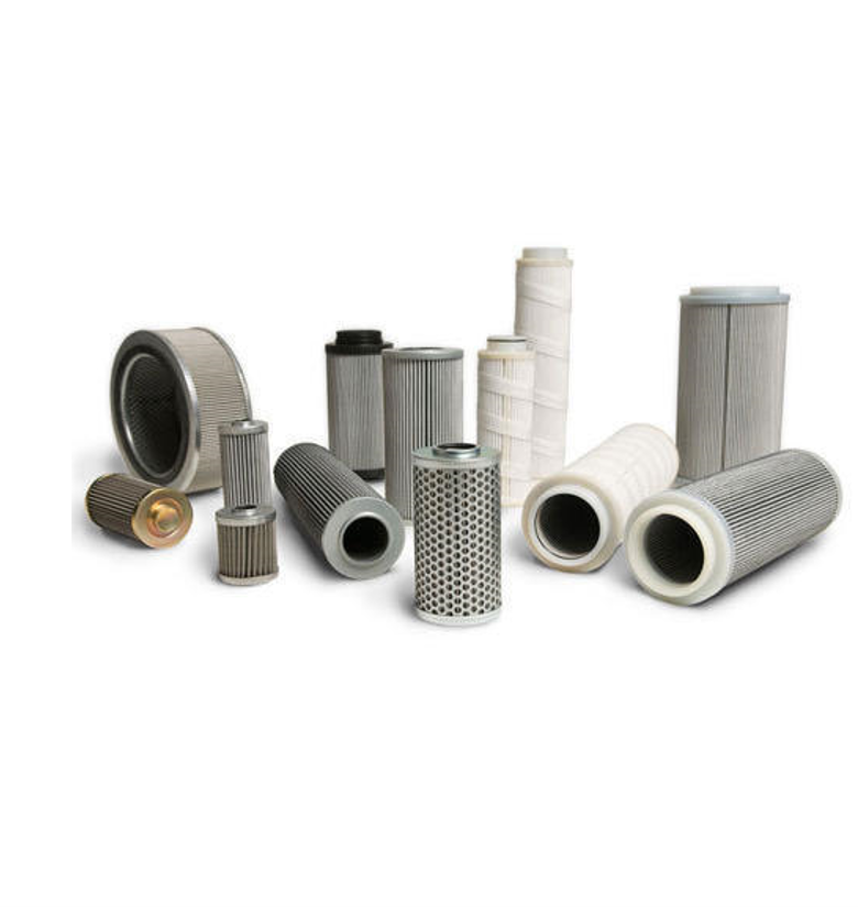
Filtration is undeniably one of the most important components in any hydraulic system. Choosing the correct hydraulic filter can increase a machine’s life expectancy and  lower the risk of expensive component damage.

Establishing the Target Cleanliness Level

We recommend identifying the most sensitive component in your system and learn the filtration cleanliness level (or micron rating) for that component. This is often a variable piston pump or the proportional valve. By using a recommended cleanliness code chart, you can determine the ISO code for a range of the most critical components such as pumps, valves, actuators, and more. From this ISO code, you can select the appropriate filter from your preferred manufacturer’s catalogue. Contact our team if you are unsure.

Achieving Target Cleanliness

There are generally four major factors in positioning contamination control devices in a hydraulic or lubrication system to achieve the target cleanliness level that is required.

Initial filter element efficiency

Filter element efficiency under system stress

Location and sizing of contamination control devices in the system

Filter element service life of the system

While all of these factors are important, filter manufacturers (such as Parker, Eaton and MP Filters) typically design their filters for maximum efficiency, so you have more responsibility to ensure the location and filter sizing is correct to increase the longevity and reduce maintenance damage to your hydraulic system. When done correctly, this will give the best service life of a system.

Selecting The Right Filter Type

Suction filters are usually put in a tank to filter out any large items, such as bolts or rags that may have dropped in the reservoir. They are not generally used for filtering your fluid to the required ISO code.

Pressure filters come highly recommended because they are placed after your pump, so if the pump was to fail, all of the components downstream would still be protected. These filters must be rated for your system’s running pressure and ISO code.

Return filters are important because they clean the oil before it returns to your hydraulic reservoir and therefore keep your reservoir clean and free from dirt particles. Return line filters are generally used in open-loop applications and should be rated at the ISO code that your system requires.

While all three filter types are generally not needed in the same system, it is important to have at least one pressure filter or one return line filter in every application to maintain the fluid cleanliness level that hydraulic components require.

Selecting The Right Filter Size

Once you determine what type of filter to use, you must consider the pressure drop through the filter. In most cases, pressure filters and return filters have a bypass that protects the system when the filter gets clogged or plugged. It allows the oil to go around the filter element and allows the system to run even though it’s not being filtered. Do keep in mind that your system would be running unfiltered with this setup.

As your filter becomes dirtier, it requires more pressure to push the oil through the element because it is clogged with dirt and debris. Once the pressure required reaches a certain point it becomes inefficient and starts wasting horsepower in the hydraulic system; this is the reason for the bypass. Typically, bypass settings on pressure filters are 40-50 PSI to limit this inefficiency.

When sizing a pressure filter, generally we would like to keep the pressure drop through the filter under 10 PSI. This gives your filter more time to get to the 50 PSI bypass setting, thus increasing the length of time between element changes. If you size your filter with a 25 PSI pressure drop you are already at half of your filter life (assuming 50 PSI bypass). If we selected a filter that only had a 10 PSI pressure drop, your filter will have 40 PSI of pressure drop before it reaches bypass setting, thus, allowing the element to last longer before needing service or be replaced.

Another consideration is oil viscosity. Thicker oil will cause a higher pressure drop, so you need to know what oil you are going to run in your system to truly size the filter correctly and get the best filter life for your application.


Effects Of Hydraulic Oil

Choosing the correct filter is only part of the equation. New hydraulic oil straight from the drum has a typical cleanliness level of ISO 4406 23/21/18. From what we learned above you can see that this is 16-64x dirtier than what most hydraulic systems require (each single number increase in the ISO code is double the contaminant level for that micron size)! To put it another way, a 25 GPM pump operating continuously in hydraulic oil at 23/21/18 will circulate 3,500 pounds of dirt to the hydraulic system’s components each year.

Extend Filter Life By Using Clean Hydraulic Oil

To add hydraulic oil, and not the dirt, always filter new oil prior to use in a hydraulic system. This can be done in a number of ways. The most common way is to use a filtration cart or kidney loop filter in your reservoir. Schroeder makes an exceptional filter cart that can not only remove dirt particulates from new oil, but also water, if needed. Carts like these offer great value for your investment, as they range from relatively low cost to expensive, depending on what you are trying to accomplish. Also, if you are already running Schroeder mobile filtration on your machine, then there is a good chance you can use the same filter element that you already use, thus reducing inventory parts.

Another way to pre-filter your hydraulic oil is by pumping the oil into the hydraulic reservoir through the system’s return filter. The easiest way to do this is to install a tee in the return line and attach a quick-connector to the branch of this tee. Attach the other half of the quick-connector to the discharge hose of a drum pump. When hydraulic oil needs to be added to the reservoir, the drum pump is coupled to the return line and the oil is pumped into the reservoir through the return filter. Benefits of this method include reduced spills and prevention of ingress of external contamination.

While many people don’t even think about filtering new oil, it is very important to get clean oil into the system. It is much easier to prevent dirt from getting into a system by using precautionary measures than it is to remove dirt from a hydraulic system. Once the dirt ingresses, it is very difficult to get the system clean.

When To Change Hydraulic Fluid

Maintaining the hydraulic fluid in your machine is an important consideration when choosing and extending the life of hydraulic filters. It’s challenging to set an expiration on hydraulic fluid introduced into your system, even under ideal circumstances. Over time even well maintained oil will wear out, however here are a few factors that affect hydraulic fluid and when filter changes are more than likely necessary.

Contamination

Contamination, in the context of having to change your hydraulic fluid, means you have debris in the fluid than the filtration system can reasonably remove. This is usually some sort of particulate contamination event that overruns the system’s onboard filtration. This can also include contaminating situations such as getting water mixed into the fluid (looks cloudy) or mistakenly topping off your hydraulic reservoir with the wrong fluid. It may be possible to salvage your particulate or water contamination situation using some sort of off-line filtration asset.

Heat

This one is simple. If you get your fluid gets too hot, it breaks down. Most of the time you know it got too hot because it becomes darker in color and it doesn’t smell right. It usually doesn’t take the time and expense of a fluid sample analysis to figure this one out. Heat accelerates the condition called oxidative degradation.

Oxidative Degradation and Additive Depletion

This one is a little more complex and will require a fluid analysis to determine. By performing routine fluid analysis a degradation or depletion trend can be spotted before it becomes a mechanical maintenance event.

A hydraulic oil’s oxidative degradation is determined by its Total Acid Number or TAN. As the name implies, this is the absolute measure of the total acid number in the fluid. Over time, oxygen will combine with the hydrocarbon molecules of the oil and a chain reaction occurs. This action results in some obvious conditions like darkened oil, varnishing, and sludge. Some conditions that are not so obvious are increased viscosity, increased foaming, and retained air.

A hydraulic oil’s additive depletion is determined by comparing the used oil’s elemental analysis to the baseline of identical new oil. For example, zinc is an antioxidant and anti-wear additive. Over time it gets depleted, so it’s important to check the concentration of zinc in your current oil to the concentration of zinc in the same new oil.

Rotec’s technical experts have many years of experience in applying the right components for maximum effectiveness and overall lower total cost of ownership. They can help you to improve efficiency and save money over the life of your equipment. Contact our team today for help in finding the correct filter and oil for your hydraulic system.

Bespoke hydraulic ring main and multiple air blast coolers installed at leading Aerospace Engineering company

Rotec Hydraulics Ltd was chosen by leading aerospace and engineering business to complete a 3-phase upgrade project to its existing Structural Test Lab (STL) hydraulic ring main. The team at Rotec successfully completed the project on time and to a high level of quality.

A global leader in Aerospace, Defence and Security, our client is a key supplier of defence and security equipment to the UK MoD, employing over 7,500 highly skilled personnel across 7 main sites throughout the UK.

A crucial asset at their Somerset facility is its Structural Test Laboratory (STL), which is responsible for mechanically testing critical aircraft components to destruction. As part of an ongoing development programme, the client wanted to create a dedicated and permanent hydraulic supply to its expanding fleet of testing equipment.

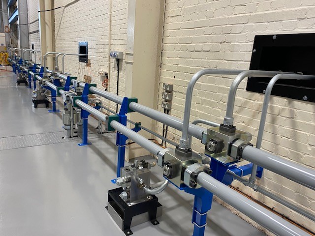
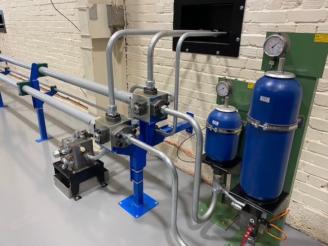
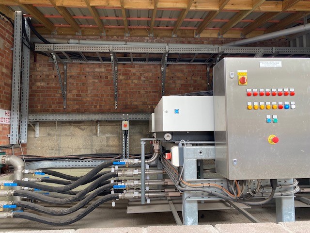
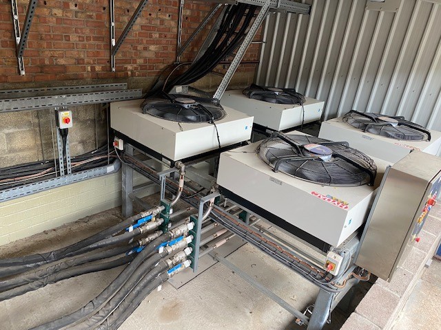
Rotec Hydraulics Ltd added several significant upgrades to the current system in three stages; install 4 air blast coolers, design and install a custom sub ring main within the new Fatigue Lab and finally to design and install a major upgrade to the existing distribution ring main.

As part of the second and final phases of the project, Rotec designed and built a number of bespoke pipework brackets, stands and manifolds all of which were FEA tested by our in-house design engineers to ensure they exceed the minimum design requirements set by the customer.

More than 21.5 metres of pressure and return pipework was manufactured on site using Parker’s unique High Pressure Flange system making for a very quick and efficient installation. The 80 x 10mm 6k steel pipework is capable of operating at 420 bar maximum working pressure and was connected using Rotec’s in-house designed “X-Blocks” which distributed the flow to numerous outputs.

Rotec’s capabilities are that of significant breadth meaning, unlike many competitors, Rotec is able to design, build, install, commission and maintain systems in-house to a consistently high standard. To find out more, visit our services page.

Rotec supports new immersive visitor experience at the Fleet Air Arm Museum

The Fleet Air Arm Museum will be wowing visitors with their new state-of-the-art, immersive Carrier Experience after a £1million refurbishment.

Rotec Hydraulics Ltd were pleased to carry out works on the hydraulic and electrical systems that are integral to the simulator experience at the museum, which houses aircraft and artefacts from the flying arm of the Royal Navy.

In addition to replacing over 50m of hydraulic hose, all hoses were uniquely identified using the Parker Hannifin PTS bar-code labelling system to ease traceability and future renewal. Rotec engineers also refurbished all hydraulic cylinders and repaired the two hydraulic pump units to ensure pressure and flow performance are maximised. Other works included replacement seals, filters and directional valves, strip and clean manifold assemblies and reservoir cleans.

Adjacent to the hydraulic works, Rotec carried out electrical works on the customer experience feature at the museum in the main pump room, remote control room and on the scissor lift which raises and lowers visitors during the simulation.

In the main pump room located control panel, Rotec removed existing obsolete Toshiba PLC unit hardware, and installed a newly supplied 24VDC 10A switch mode power supply module plus protective devices. A rewire the existing safety monitoring control relay and circuit was required to provide a dual channel redundant protective emergency stop circuit.

Rotec designed, supplied and installed replacement PLC hardware to replace the Toshiba module, which was then fully programmed with the required application specific logic code to ensure the scissor lift would rise and lower in time with the attraction’s audio-visual experience.

In the remote control room, Rotec supplied and installed an operator’s control station and local 24VDC power supply. The control station included a nominal 8” full colour touchscreen HMI device fully programmed with all existing and planned operator controls, indicators and alarms.

The works Rotec has completed in part of an overarching Carrier Experience. The new experience, which is dedicated to the memory of generous benefactor Vice Admiral Sir Donald Gosling KCVO, Vice Admiral of The United Kingdom, combines digital technology with the scale of a carrier flight deck to transport visitors from the pioneer years of the First World War, all the way to the modern HMS Queen Elizabeth class carriers of today.

Adam Gosling, of the Gosling Foundation comments,

“Vice Admiral Sir Donald Gosling KCVO, Vice Admiral of The United Kingdom founded the original Carrier Experience that opened in 1994 and has welcomed over four million visitors.


“To see the Experience reinvigorated and made meaningful and relevant for today’s audience is the perfect way to celebrate my late father’s enduring support of the Fleet Air Arm Museum. It reflects a mutual vision to preserve and showcase the proud history of British naval aviation. His generous legacy gift has enabled, once again, the illustrious tale of Britain’s aircraft carriers to be told, and enjoyed, for many more generations to come.”

Professor Dominic Tweddle, Director General of The National Museum of the Royal Navy says,

“The re-imagining of the Carrier Experience to include the Queen Elizabeth Class, the pride of the British fleet, demonstrates our ongoing commitment to the history of naval aviation and telling the story of the contemporary navy. This mix of heritage and modernity mirrors the projects that Vice Admiral Sir Donald Gosling KCVO, Vice Admiral of the United Kingdom so generously supported over the years.


“I am certain that the work of the staff team, contractors and corporate partner Lockheed Martin has brought to life the Carrier story in the way that Sir Donald had in mind when he made his legacy gift.  It is both an honour and a pleasure to recognise his lifelong support with this exhibition, which is housed in The Gosling Hall.”

Rotec were chosen to complete the works due to their impressive ability to combine hydraulics with complex electronic control systems. The works were completed in a matter of weeks, on schedule and to a high standard.

For further information on the expansive range of services Rotec offers, including case studies of other works, visit www.rotec.net.

Ground-breaking Project successfully crosses the Atlantic Ocean

A pioneering project, supported by Rotec Hydraulics Ltd, has achieved a fully autonomous ship sail across the Atlantic Ocean.

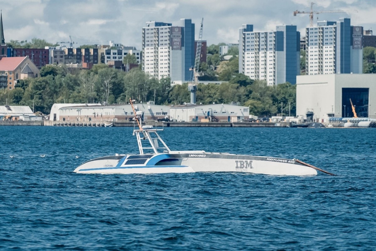
Solo and unaided, the Mayflower Autonomous Research Ship (MAS) set sail from Plymouth harbour in the UK and reached its end destination of Plymouth USA on 30th June 2022 after 36 days at sea and 3,900 miles, having made two stops in Horta (Azores) and Halifax (Canada).

The futuristic vessel was powered by AI and powered using renewable solar energy technology, and a backup diesel generator for night sailing. Throughout the journey, the vessel collected data that researchers hope will provide critical information in the battle to safeguard the future of our oceans. A challenging project relied on a diverse team that spanned 10 countries and 3 continents, including Rotec Hydraulics Ltd.

ProMare, a US based non-profit organisation with a branch in Plymouth UK, teamed up with IBM to build the third Mayflower and asked Rotec to supply a range of hoses and hose assemblies to support the project. Rotec was also pleased to be able to help spread the word of crowdfunding efforts at the start of the project.

Brett Phaneuf, Managing Director of the MAS Project, commented:

 “[The Mayflower Project is] ushering us into a new phase of oceanographic and climatological research with state-of-the-art technology.”

Paddy Dowsett – Project Manager, MSubs says:

“This project brings a number of new  technologies together in a way that hasn’t been done before. There are some smaller autonomous crafts in existence, however nothing anywhere near this scale in terms of size and technicality.”

Find out more about the project, including live video stream when the vehicle is on a mission and footage from previous journeys at https://www.mas400.com/.